








Published Fri 2nd Oct 2026
This project was presented in the September 2026 edition of Der Eisenbahningenieur in connection with InnoTrans 2026, and has appeared in the 2026 ALLSAT Journal
More than 1,000 wireless sensors. Around 6 km of railway track. Continuous monitoring of a site affected by historic mining.
The Gröbers railway junction in Germany presents a specific geotechnical challenge: monitoring railway infrastructure built above historic underground mining workings, where ground settlement and sinkhole formation remain potential hazards.
To address this, Deutsche Bahn InfraGO AG commissioned a replacement for the site's original sinkhole detection system, using Senceive wireless triaxial tilt sensors installed directly onto railway sleepers. Implemented by Senceive's partner ALLSAT GmbH, the new system used wireless remote monitoring to provide ongoing insight into changes in track geometry.
But how do the sensors help identify potential settlement beneath a railway? And how are individual measurements transformed into information that engineers can use?
The challenge: monitoring above historic mine workings
The Gröbers railway junction lies northeast of the village of Gröbers, between Halle (Saale) and Leipzig. The railway crosses areas affected by the former Clara Verein lignite mine, where underground mining took place between 1852 and 1928 at a depth of approximately 30 metres.
Over time, the timber supports within the abandoned mine workings have deteriorated, creating the potential for the overlying ground to collapse. This can result in settlement depressions or, in more severe cases, surface collapses.
To manage this risk, a geogrid-reinforced ground structure and a dedicated sinkhole detection system were installed above the former mining area between 2000 and 2002.
However, the electronic components embedded in the ground began to age and required increasingly intensive maintenance. Because replacing them would involve extensive intervention in the subsurface, DB InfraGO AG sought an alternative monitoring approach using sensors installed closer to the surface.
The solution needed to monitor the affected railway tracks without requiring another large-scale excavation of the ground.
Installing 1,026 wireless sensors across 6 km of track
Following a public tender, ALLSAT GmbH was commissioned to implement the replacement system using Senceive wireless inclination monitoring technology.
A total of 1,026 Triaxial Tilt sensors were installed on the sleepers across approximately 6 km of railway track, covering an area of around 7 hectares.
The sensors are positioned at intervals of approximately 6 metres, equivalent to ten sleepers. This spacing provides a distributed network of measurement points along the affected tracks.
Each sensor measures changes in inclination along the two horizontal axes, providing information about changes in the track's longitudinal and transverse geometry. The sensors have a measurement resolution of 0.0001°, equivalent to approximately 0.00175 mm/m in angular gradient terms.
An integrated temperature sensor also provides data to support the understanding of temperature-related effects on track measurements.
Measurements are taken at 60-minute intervals, enabling the system to track changes over time rather than relying solely on individual site inspections or periodic survey observations.
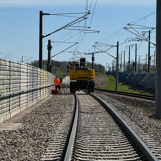
Tilt sensors installed on sleepers at the Gröbers railway junction. Source: Florian Schäfer, Allsat
Installation considerations
The tilt sensors were usually installed during nighttime track closures or train breaks. During installation, an additional track survey was carried out using a tachymeter and track gauge.
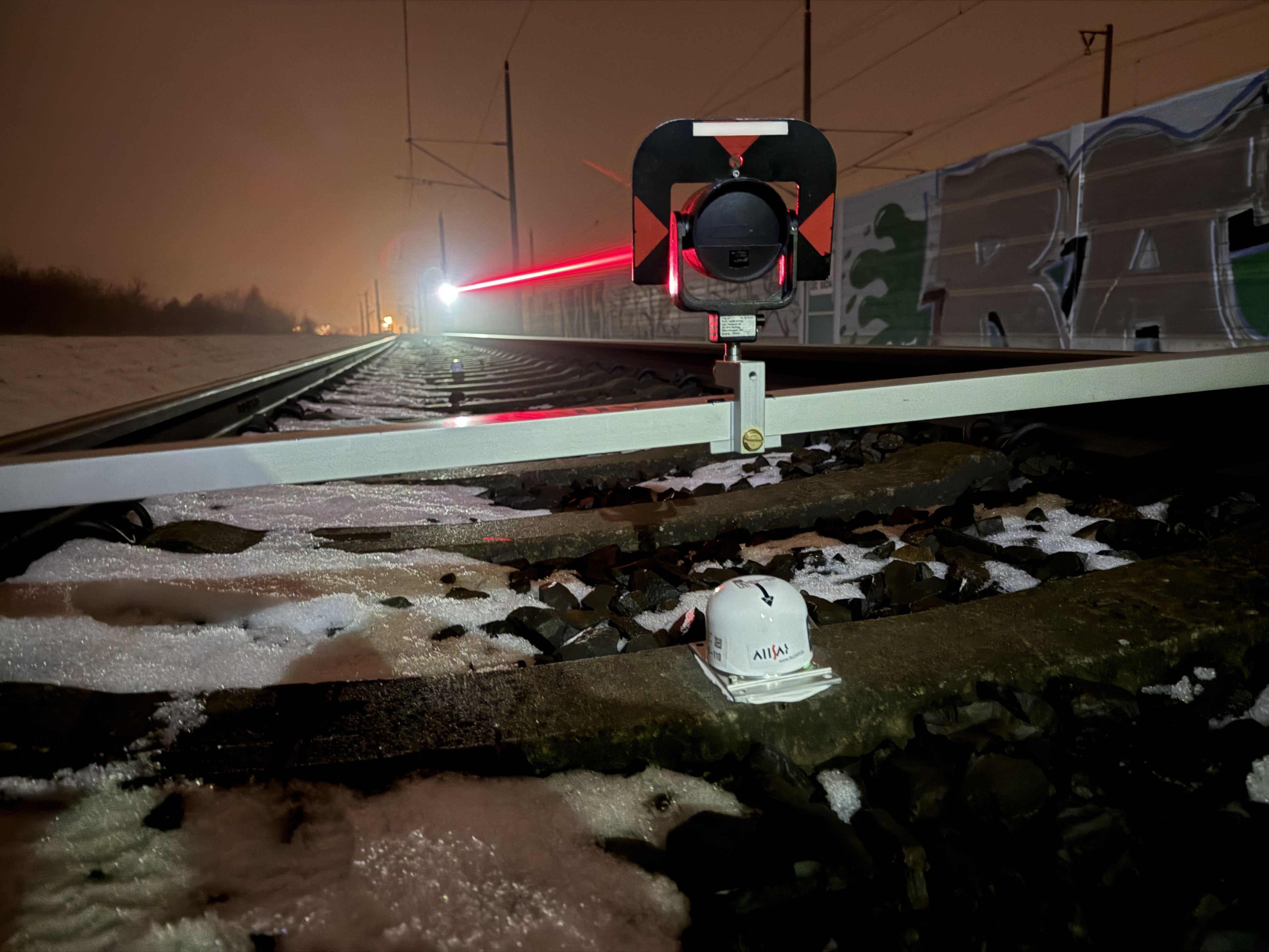
Installed tilt sensor with a track gauge placed above it. The laser pointer of the total station is visible while the prism is being measured. Source: Florian Schäfer, Allsat
The materials for installing the tilt sensors and for the tachymetric track survey were moved along the track using a small transport wagon. Before the sensor could be glued to the sleeper with adhesive, the sleeper had to be cleaned and partially cleared of snow and ice. The sensor, including a two-part base plate, was then glued to the sleeper. The two-part base plate allows the sensor to be temporarily removed without having to remove the glued-on lower part. This may be necessary, for example, when a track re-entry point needs to be created or when mechanical tamping work with ballast brushes is being carried out.
How the sensor calculation works
For settlement detection, the evaluation method considers three adjacent sensors.
The relative vertical displacement of the middle sensor is determined in relation to the two outer sensors. By assessing how the longitudinal inclination changes across neighbouring measurement points, the system can identify variations in the track's vertical profile.
This approach is particularly relevant to the detection of settlement depressions. Rather than relying on a single sensor to indicate movement at one location, measurements from neighbouring points help characterise the shape of the deformation along the track.
The angular measurements are converted into metric values through trigonometric calculations, allowing the data to be interpreted in terms of railway geometry.
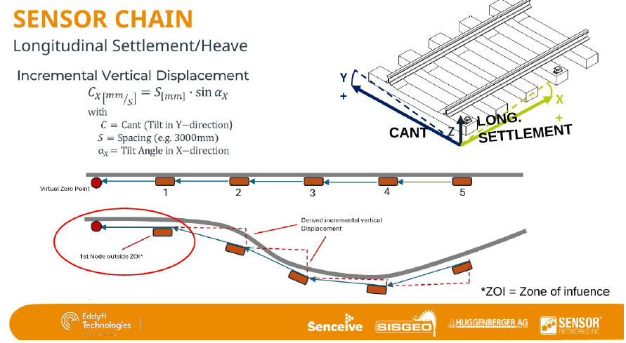
Longitudinal settlement chain with zone-of-influence concept. (Eddyfi Technologies RMS)
Why sensor spacing matters
Sensor spacing is therefore not merely an installation decision – it is an important part of the calculation. Shorter spacing provides a better representation of local curvature, while larger spacing progressively smooths the deformation profile.
This principle is particularly relevant at Gröbers, where the objective is to identify the geometry of a developing settlement depression rather than simply measure movement at an isolated point. At Gröbers, the sensors are installed at approximately 6-metre intervals. This spacing forms part of the measurement configuration and the subsequent evaluation of the track profile.
The spacing between measurement points influences how the geometry of a developing deformation is represented. The resulting assessment depends on the relationship between neighbouring measurements, rather than on isolated readings alone.
The monitoring objective is therefore not simply to record changes in inclination, but to use those measurements to identify changes in the track geometry that may indicate a developing settlement depression.
FlatMesh communications platform
Collecting measurements across more than 1,000 sensors is only one part of the monitoring system. Those measurements must also be transmitted reliably from the railway to software platform where they can be reviewed.
The data pathway consists of four stages:
- Sleeper-mounted sensors: The inclination sensors record data at 60-minute intervals
- FlatMesh wireless network: Sensor measurements are relayed through the wireless network
- LTE gateways: A network of 16 gateways receives the measurements (positioning of the gateways was an important factor
- Senceive WebMonitor: The data is presented through a web-based interface, allowing authorised users to review measurements and monitor changes over time.
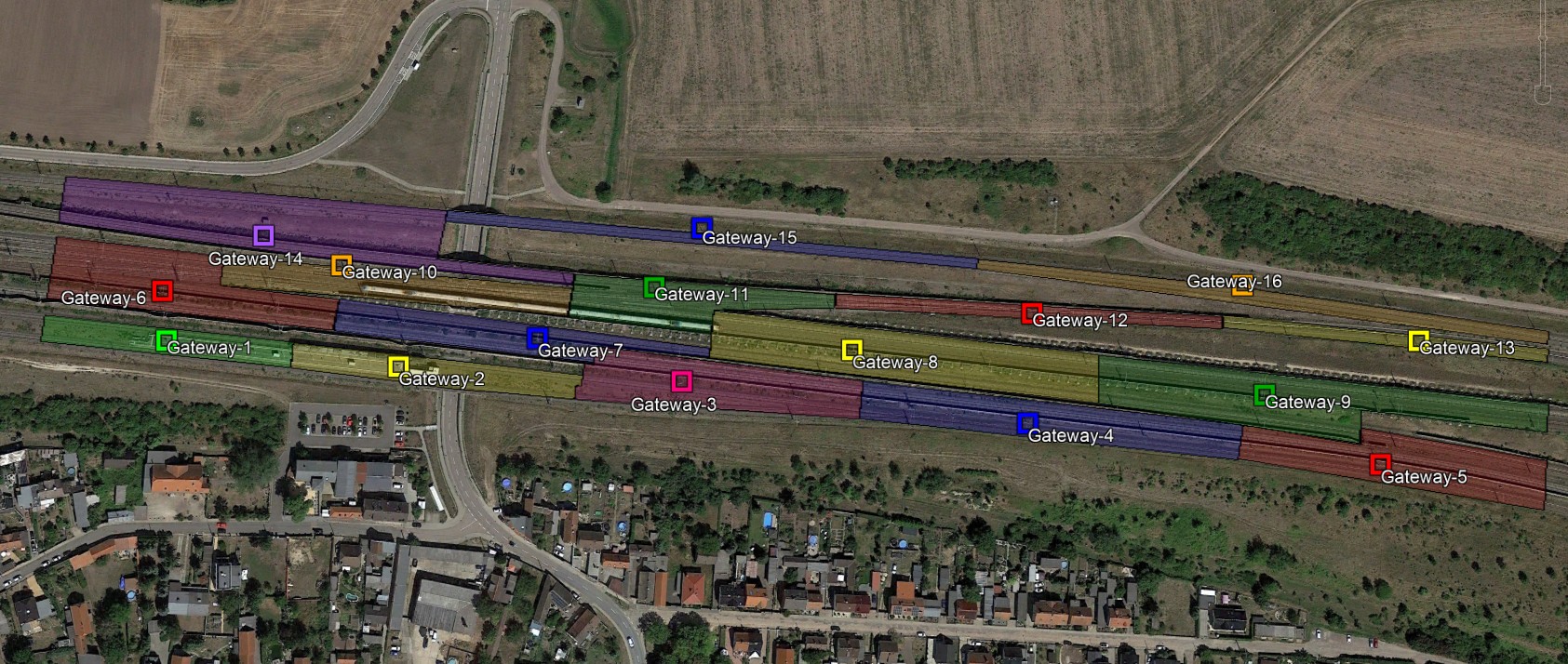
The coloured polygons represent the different sensor networks. The position of the corresponding gateway is marked as a square in the same color. Source: Florian Schäfer, Allsat
The gateways are powered by solar panels and integrated batteries, while the sensors use internal batteries designed for a service life of up to 12 years. This enables the monitoring installation to operate autonomously.
Senceive's WebMonitor platform provides authorised users with a graphical overview of the monitoring area, alongside time-series data for individual measurements. This allows changes to be reviewed over time and helps users understand how the monitored track is behaving.